http://www.electronicshub.org/ir-sensor/
- Near infrared region — 700 nm to 1400 nm — IR sensors, fiber optic
- Mid infrared region — 1400 nm to 3000 nm — Heat sensing
- Far infrared region — 3000 nm to 1 mm — Thermal imaging
The frequency range of infrared is higher than microwave and lesser than visible light.
For optical sensing and optical communication, photo optics technologies are used in the near infrared region as the light is less complex than RF when implemented as a source of signal. Optical wireless communication is done with IR data transmission for short range applications.
An infrared sensor emits and/or detects infrared radiation to sense its surroundings.
The working of any Infrared sensor is governed by three laws: Planck’s Radiation law, Stephen – Boltzmann law and Wien’s Displacement law.
Planck’s law states that “every object emits radiation at a temperature not equal to 00K”. Stephen – Boltzmann law states that “at all wavelengths, the total energy emitted by a black body is proportional to the fourth power of the absolute temperature”. According to Wien’s Displacement law, “the radiation curve of a black body for different temperatures will reach its peak at a wavelength inversely proportional to the temperature”.
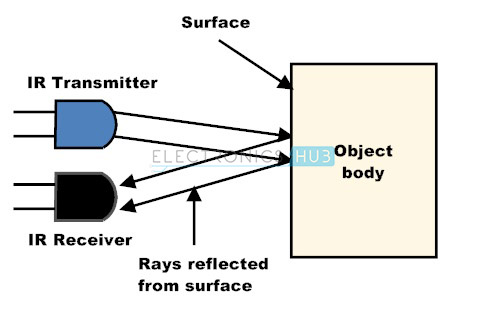
The basic concept of an Infrared Sensor which is used as Obstacle detector is to transmit an infrared signal, this infrared signal bounces from the surface of an object and the signal is received at the infrared receiver.
There are five basic elements used in a typical infrared detection system: an infrared source, a transmission medium, optical component, infrared detectors or receivers and signal processing. Infrared lasers and Infrared LED’s of specific wavelength can be used as infrared sources. The three main types of media used for infrared transmission are vacuum, atmosphere and optical fibers. Optical components are used to focus the infrared radiation or to limit the spectral response. Optical lenses made of Quartz, Germanium and Silicon are used to focus the infrared radiation. Infrared receivers can be photodiodes, phototransistors etc. some important specifications of infrared receivers are photosensitivity, detectivity and noise equivalent power. Signal processing is done by amplifiers as the output of infrared detector is very small.
Types of IR Sensors
Infrared sensors can be passive or active. Passive infrared sensors are basically Infrared detectors. Passive infrared sensors do not use any infrared source and detects energy emitted by obstacles in the field of view. They are of two types: quantum and thermal. Thermal infrared sensors use infrared energy as the source of heat and are independent of wavelength. Thermocouples, pyroelectric detectors and bolometers are the common types of thermal infrared detectors.
Quantum type infrared detectors offer higher detection performance and are faster than thermal type infrared detectors. The photosensitivity of quantum type detectors is wavelength dependent. Quantum type detectors are further classified into two types: intrinsic and extrinsic types. Intrinsic type quantum detectors are photoconductive cells and photovoltaic cells.
Active infrared sensors consist of two elements: infrared source and infrared detector. Infrared sources include an LED or infrared laser diode. Infrared detectors include photodiodes or phototransistors. The energy emitted by the infrared source is reflected by an object and falls on the infrared detector.
IR Transmitter
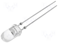
Infrared Transmitter is a light emitting diode (LED) which emits infrared radiations. Hence, they are called IR LED’s. Even though an IR LED looks like a normal LED, the radiation emitted by it is invisible to the human eye.
The picture of a typical Infrared LED is shown below.
There are different types of infrared transmitters depending on their wavelengths, output power and response time.
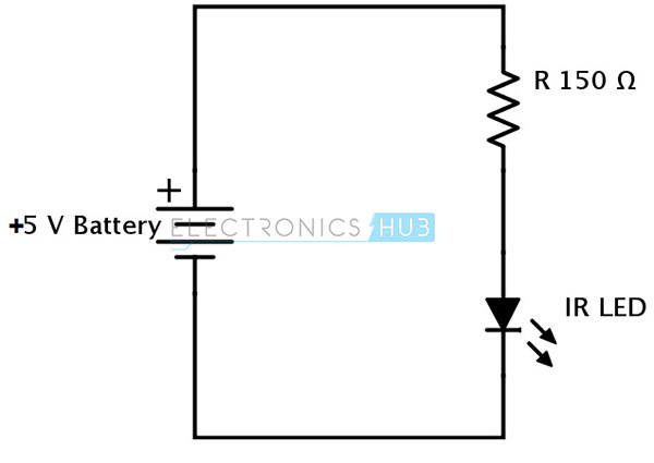
A simple infrared transmitter can be constructed using an infrared LED, a current limiting resistor and a power supply. The schematic of a typical IR transmitter is shown below.
When operated at a supply of 5V, the IR transmitter consumes about 3 to 5 mA of current. Infrared transmitters can be modulated to produce a particular frequency of infrared light. The most commonly used modulation is OOK (ON – OFF – KEYING) modulation.
IR transmitters can be found in several applications. Some applications require infrared heat and the best infrared source is infrared transmitter. When infrared emitters are used with Quartz, solar cells can be made.
IR Receiver
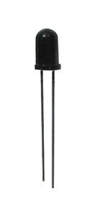
Infrared receivers are also called as infrared sensors as they detect the radiation from an IR transmitter. IR receivers come in the form of photodiodes and phototransistors. Infrared Photodiodes are different from normal photo diodes as they detect only infrared radiation. The picture of a typical IR receiver or a photodiode is shown below.
Different types of IR receivers exist based on the wavelength, voltage, package, etc. When used in an infrared transmitter – receiver combination, the wavelength of the receiver should match with that of the transmitter.
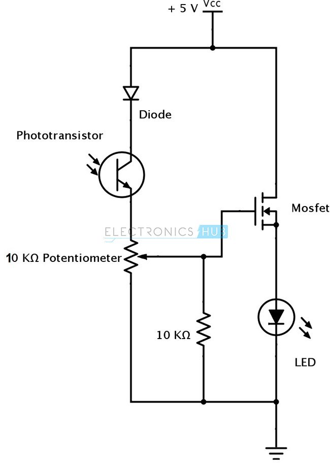
A typical infrared receiver circuit using a phototransistor is shown below.
It consists of an IR phototransistor, a diode, a MOSFET, a potentiometer and an LED. When the phototransistor receives any infrared radiation, current flows through it and MOSFET turns on. This in turn lights up the LED which acts as a load. The potentiometer is used to control the sensitivity of the phototransistor.
Principle of Working
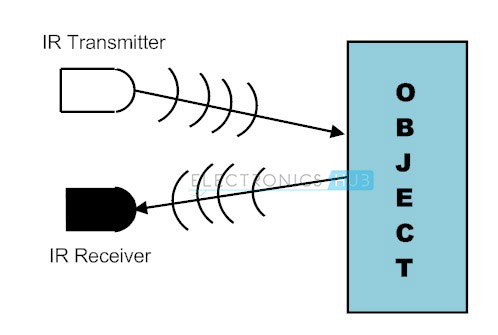
The principle of an IR sensor working as an Object Detection Sensor can be explained using the following figure. An IR sensor consists of an IR LED and an IR Photodiode; together they are called as Photo – Coupler or Opto – Coupler.
When the IR transmitter emits radiation, it reaches the object and some of the radiation reflects back to the IR receiver. Based on the intensity of the reception by the IR receiver, the output of the sensor is defined.
Obstacle Sensing Circuit or IR Sensor Circuit
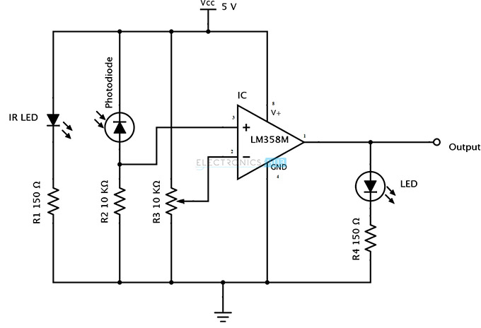
A typical IR sensing circuit is shown below.
It consists of an IR LED, a photodiode, a potentiometer, an IC Operational amplifier and an LED.
IR LED emits infrared light. The Photodiode detects the infrared light. An IC Op – Amp is used as a voltage comparator. The potentiometer is used to calibrate the output of the sensor according to the requirement.
When the light emitted by the IR LED is incident on the photodiode after hitting an object, the resistance of the photodiode falls down from a huge value. One of the input of the op – amp is at threshold value set by the potentiometer. The other input to the op-amp is from the photodiode’s series resistor. When the incident radiation is more on the photodiode, the voltage drop across the series resistor will be high. In the IC, both the threshold voltage and the voltage across the series resistor are compared. If the voltage across the resistor series to photodiode is greater than that of the threshold voltage, the output of the IC Op – Amp is high. As the output of the IC is connected to an LED, it lightens up. The threshold voltage can be adjusted by adjusting the potentiometer depending on the environmental conditions.
The positioning of the IR LED and the IR Receiver is an important factor. When the IR LED is held directly in front of the IR receiver, this setup is called Direct Incidence. In this case, almost the entire radiation from the IR LED will fall on the IR receiver. Hence there is a line of sight communication between the infrared transmitter and the receiver. If an object falls in this line, it obstructs the radiation from reaching the receiver either by reflecting the radiation or absorbing the radiation.
Distinguishing Between Black and White Colors
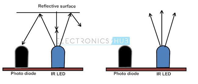
It is universal that black color absorbs the entire radiation incident on it and white color reflects the entire radiation incident on it. Based on this principle, the second positioning of the sensor couple can be made. The IR LED and the photodiode are placed side by side. When the IR transmitter emits infrared radiation, since there is no direct line of contact between the transmitter and receiver, the emitted radiation must reflect back to the photodiode after hitting any object. The surface of the object can be divided into two types: reflective surface and non-reflective surface. If the surface of the object is reflective in nature i.e. it is white or other light color, most of the radiation incident on it will get reflected back and reaches the photodiode. Depending on the intensity of the radiation reflected back, current flows in the photodiode.
If the surface of the object is non-reflective in nature i.e. it is black or other dark color, it absorbs almost all the radiation incident on it. As there is no reflected radiation, there is no radiation incident on the photodiode and the resistance of the photodiode remains higher allowing no current to flow. This situation is similar to there being no object at all.
The pictorial representation of the above scenarios is shown below.
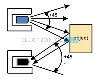
The positioning and enclosing of the IR transmitter and Receiver is very important. Both the transmitter and the receiver must be placed at a certain angle, so that the detection of an object happens properly. This angle is the directivity of the sensor which is +/- 45 degrees.
The directivity is shown below.
In order to avoid reflections from surrounding objects other than the object, both the IR transmitter and the IR receiver must be enclosed properly. Generally the enclosure is made of plastic and is painted with black color.